Lenco Trim Tab Switch Wiring Diagram / How To Fix Upgrade Trim Tabs
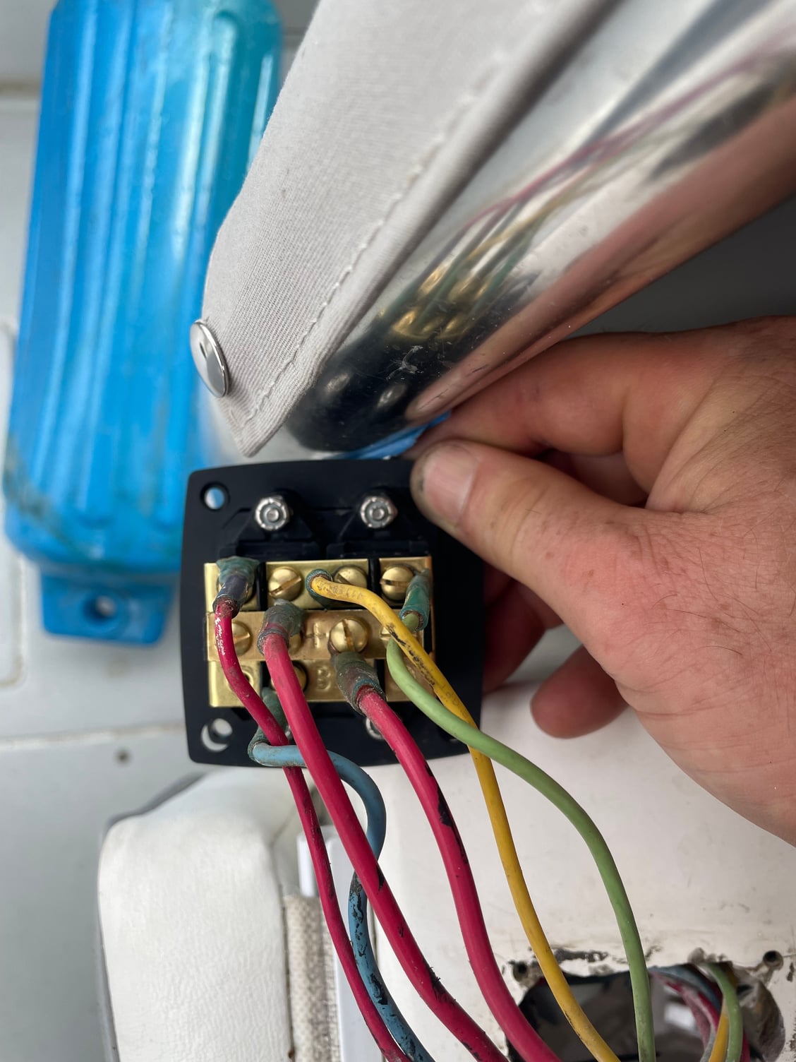
per the diagram below. console. 3) Test the trim tabs for proper operation. that the right switch controls the left trim tab and the left controls the right. Bow down should extend the tabs while bow up should retract them. If for some reason this does not work as described in the above text then recheck all the wiring for a misplaced wire.
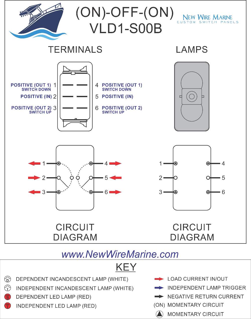
Trim Tabs Rocker Switch Carling Contura II Illuminated Accessory
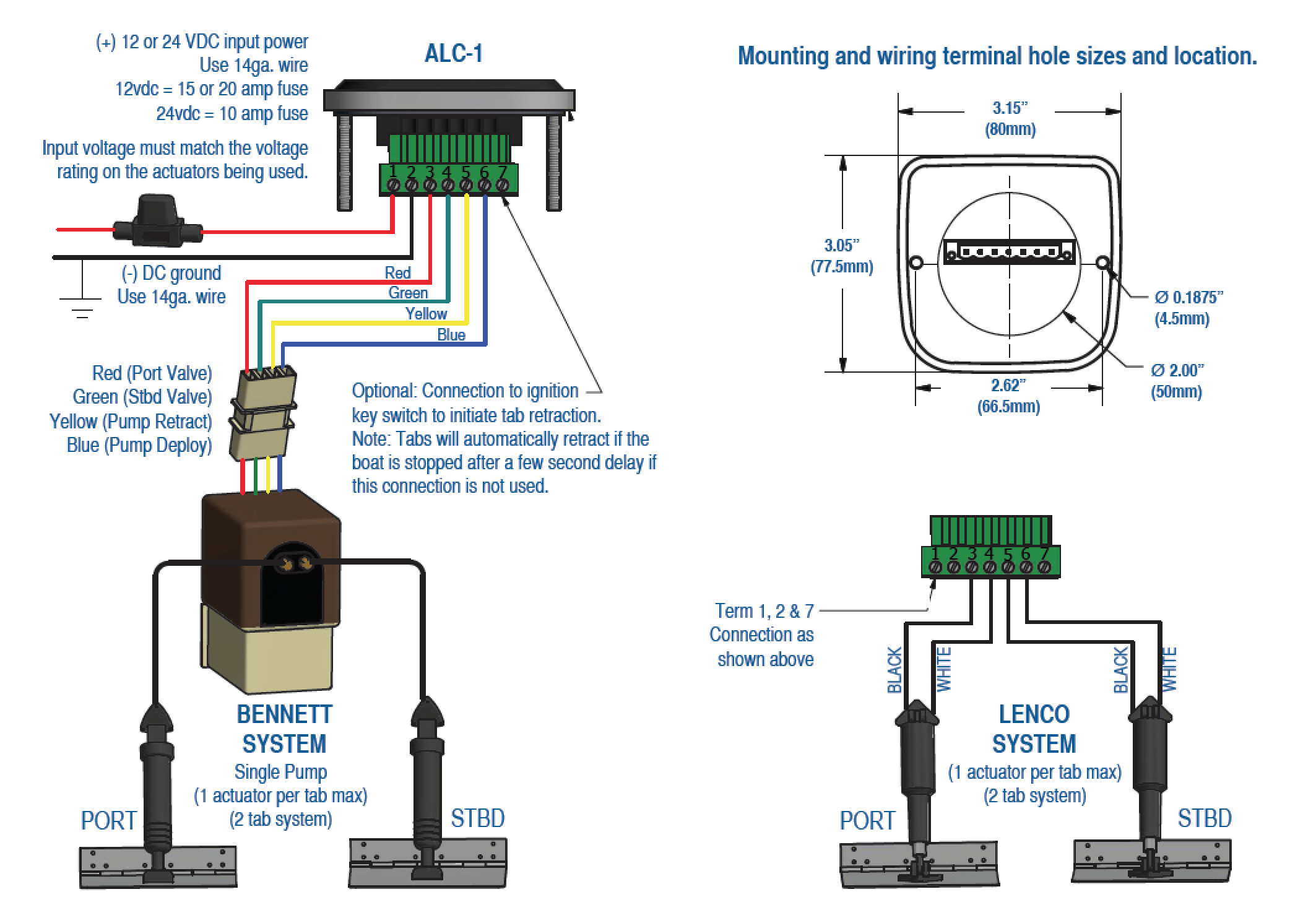
Wiring Diagrams | Lectrotab Electromechanical Trim Tab Systems Joystick LED Control (JLC-11) Flat Rocker Switch (SAF-SC and SAF-NSC) One-Touch LED (SLC-11) Manual Leveling Control (MLC-1) Auto Leveling Control (ALC-1) Auto Leveling Control (ALC-1D/2D) NMEA 2000 Connection to SLC One-Touch LED Control Discontinued: Oval Control (SETR-61)
ES2000 Trim Tab Switch Wiring on Contender The Hull Truth
Trim tab switch wiring is an essential component of trim tab systems, which are used to adjust the position of boat or ship fins to optimize stability and control. Understanding the basics of trim tab switch wiring is crucial for properly installing and operating these systems.
Lenco Trim Tab Switch Wiring Diagram
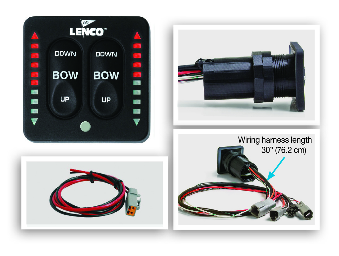
Watch this installation video for the Lenco Edge Mount trim tab kit and LED Integrated (ALL-IN-ONE) Switch kit on this 23ft Albury brothers center console boat.

Lenco Trim Tab Switch Wiring Diagram
The Benefits of Trim Tabs Increase Visibility For A Safer Ride:Keeping your bow down at reduced speeds is important, especially in congested waters or foul weather. Bennett trim tabs enable you to plane at a much lower speed, operating your boat more safely.
Lenco Trim Tab Switch Wiring Diagram Wiring Diagram Schemas
When the trim tab rocker switch is pressed, electrical current is sent to the hydraulic motor pump unit. This signal activates the electic motor, creating fluid pressure. Valves on motor pump unit open, channeling the required amount of fluid to the actuators.
Trim Tab Switch Wiring Diagram Unity Wiring
Step 1 — Position the trim tabs against the transom and check to see that the upper mounts of the hydraulic actuators do not center on an inside obstruction. If they do, reposition tabs slightly outboard. The further outboard the tabs are mounted, the greater the lateral (side-to-side) control.
Lenco Trim Tab Switch Wiring Diagram Wiring Diagram Schemas
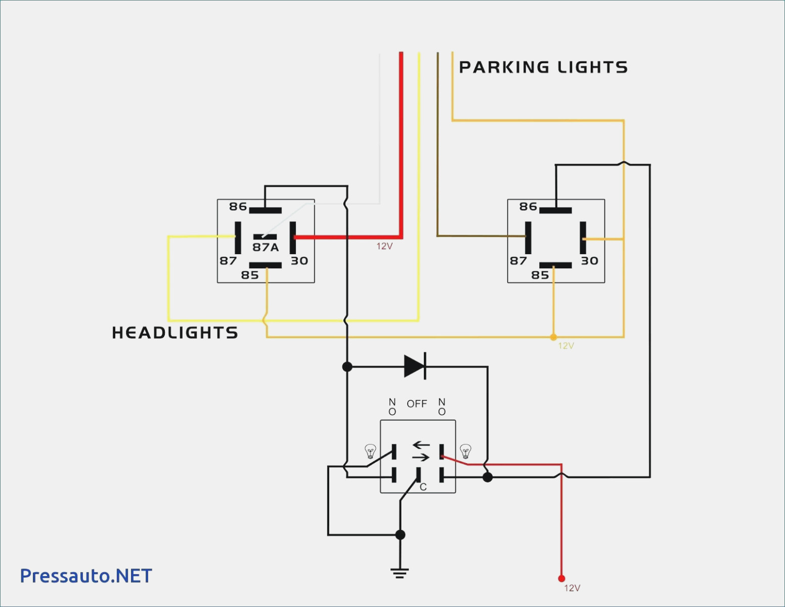
The wiring diagram provides a visual representation of how the trim tabs should be wired to the control switches and power source. The Lenco trim tabs wiring diagram typically includes the following components and connections: Trim tab motors: These are the motors that control the movement of the trim tabs.
Lenco Trim Tab Switch Wiring Diagram Wiring Diagram Schemas
Depending on your tab model, if equipped with an electric sensor, only drill one hole for the wire access thru the transom. Mount the tab: If the Livorsi Trim Tabs are replacing existing tabs, make sure to seal any unnecessary holes on the transom. Use a high quality marine sealer suitable for underwater use.

Trim Tab Switch Wiring Diagram Light Switch Wiring Diagram
Lectrotab trim tabs improve fuel efficiency, increase boat speed, accelerate shallow water planing, eliminate porpoising, and enhance the overall boating experience with a more comfortable ride. Improved Fuel Efficiency and Faster Speeds Most importantly, the trim tabs may be adjusted to optimize speed and fuel efficiency.

trim tab switch wiring diagram
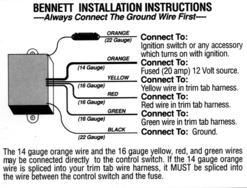
Have questions? We're here to help. Visit BennettTrimTabs.com or call (954)427-1400. Wiring Diagram Ground (Black) (Purple) ATR/Ignition Power Helm Power (Thicker Orange, or Red) 6 ft. (Orange) 3 ft. 3 ft. Twisted Extension Cable (Variable Length) 6 ft. Actuators & Tabs
lenco trim tabs wiring diagram
1. Adjust the trim tabs to achieve a planing attitude. 2. Use the power trim to position the prop path parallel to the water flow as indicated by increased RPM / Speed. 3. If necessary, re-adjust the trim tabs to fine tune the trim of your boat. In other words, use your trim tabs to trim the boat and your power trim to trim your prop.
20 Inspirational Trim Tab Switch Wiring Diagram
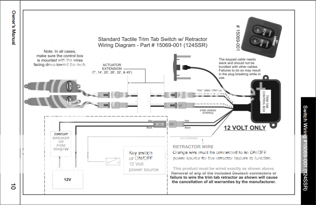
LED. Trim Tab Indicator Switch w/ Retractor and Self-Check Wiring Diagram - Part # 15070-001 (123SC) Note: In all cases, make sure the control box is mounted with the wires facing down toward the deck. CIRCUIT BREAKER OR FUSE 20A@12V IOA@24V 12V OR 24V ACTUATOR EXTENSION (7', 14', 20', 26', 32', & 45') Black The keypad cable needs
trim tab switch wiring diagram
Have questions? We're here to help. Visit BennettTrimTabs.com or call (954)427-1400. Wiring Diagram Rocker Control Yellow 7/64" Green Red Blue Blue Pump pressure HPU (Pump) (Trim tabs down)

Trim Tabs Switch Wiring Diagram Wiring Digital and Schematic
trim tabs, use short momentary taps of the switch. To become knowledgeable on how your boat performs with Lenco Trim Tabs, remember, practice makes perfect. When the tabs are lowered, the water flow is redirected, creating an upward force at the stern of the boat. Without Trim Tabs With Trim Tabs TRIM TAB OVERVIEW SWITCH OVERVIEW
Trim Tab Rocker Switch Wiring Diagram
In this video I replace the Insta Trim Boat Leveler hydraulic pump and helm switches.