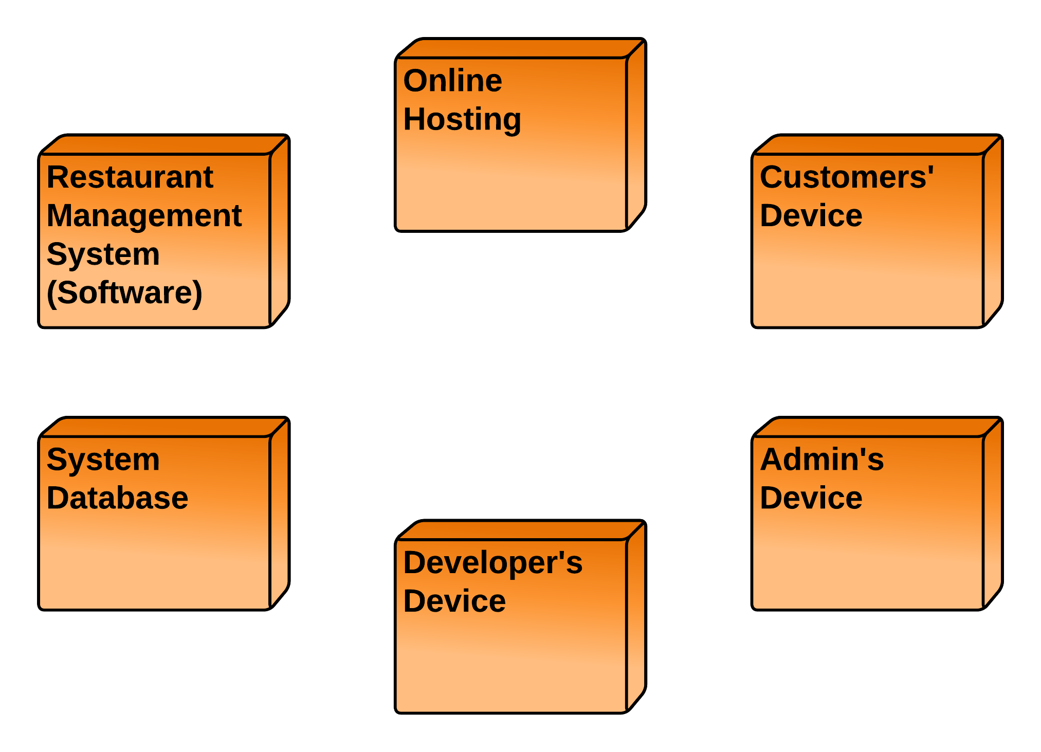
Deployment Diagram for Restaurant Management System UML
Component diagram for Restaurant Management System. The diagram below shows the structural relations between components in a Restaurant Management System. The connected components by lines represent relationships within the systems. In the diagram, it can be seen that there are components namely Restaurant, booking, customer, and account.
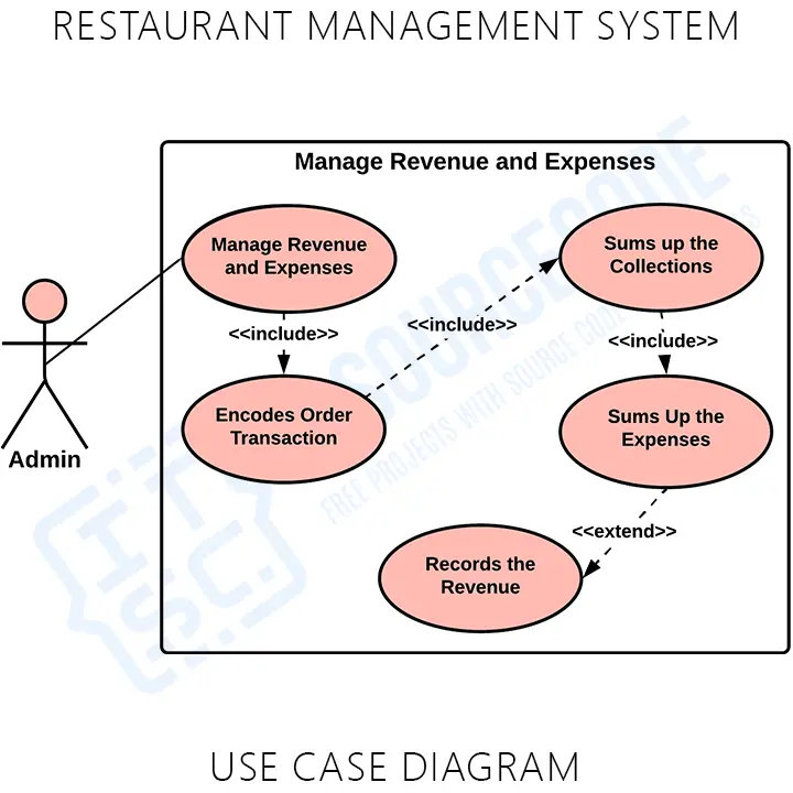
Use Case Diagram for Restaurant Management System
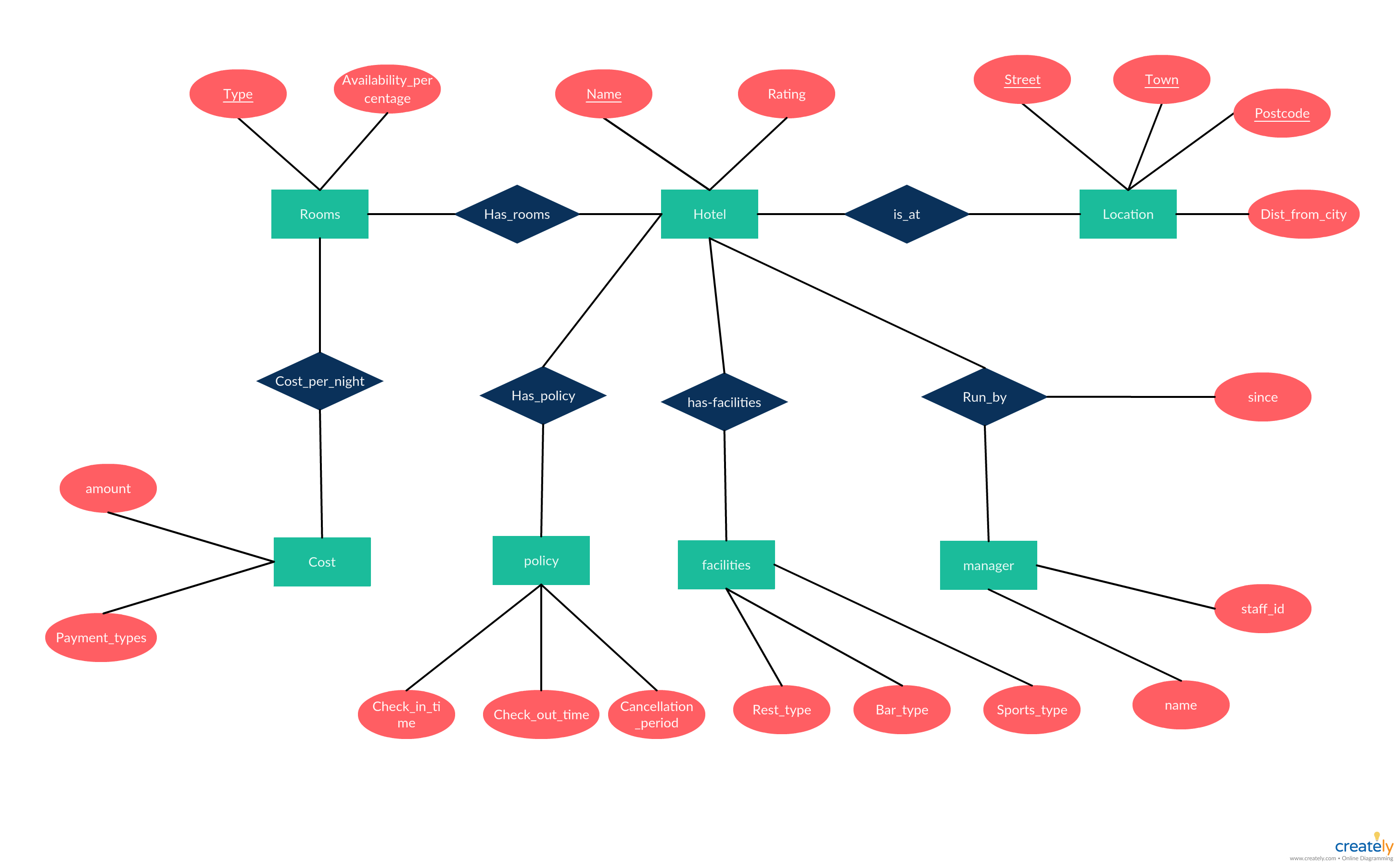
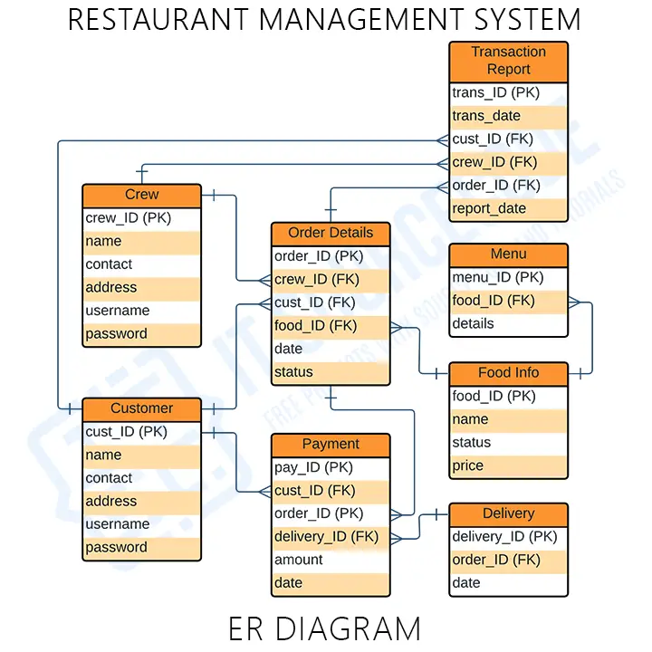
Here are the steps on how to create Restaurant Management System ER Diagram. Step 1: Become acquainted with the ER Diagram (Entity Relationship Diagram) The Entity Relationship Diagram shows the structure of data types in a project. It uses symbols to clarify its parts and relationships.
Er Diagram Restaurant Management System
Following are the steps you can follow when drawing a component diagram. Step 1: figure out the purpose of the diagram and identify the artifacts such as the files, documents etc. in your system or application that you need to represent in your diagram. Step 2: As you figure out the relationships between the elements you identified earlier.
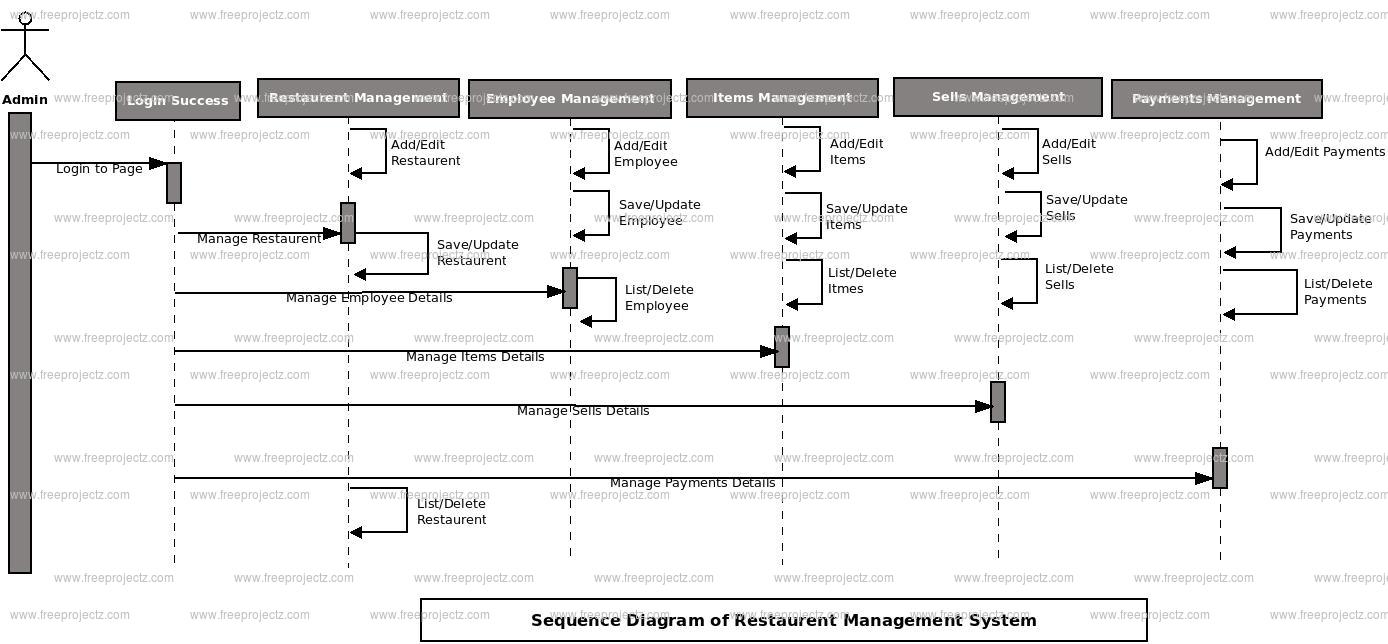
Restaurent Management System Sequence UML Diagram FreeProjectz
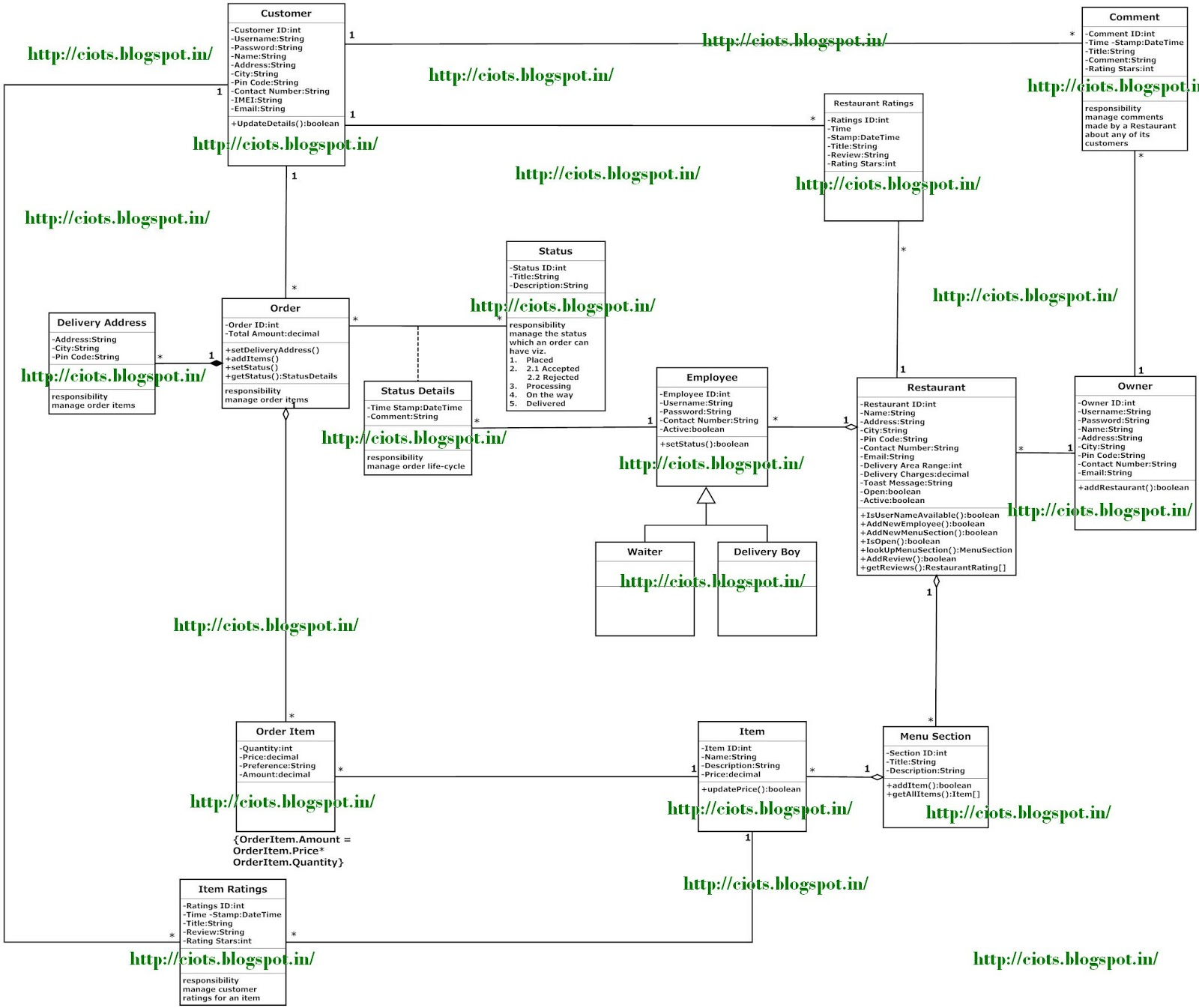
With a restaurant management system, businesses can more effectively manage orders, boost their sales and customer satisfaction, and maximize their profits. You can easily edit this template using Creately's class diagrams tool. You can export it in multiple formats like JPEG, PNG and SVG and easily add it to Word documents, Powerpoint (PPT.
Er Diagram For Restaurant Management System
Component Diagram for Restaurant. Use Creately's easy online diagram editor to edit this diagram, collaborate with others and export results to multiple image formats. You can easily edit this template using Creately. You can export it in multiple formats like JPEG, PNG and SVG and easily add it to Word documents, Powerpoint (PPT.

Restaurent Management System UML Diagram FreeProjectz
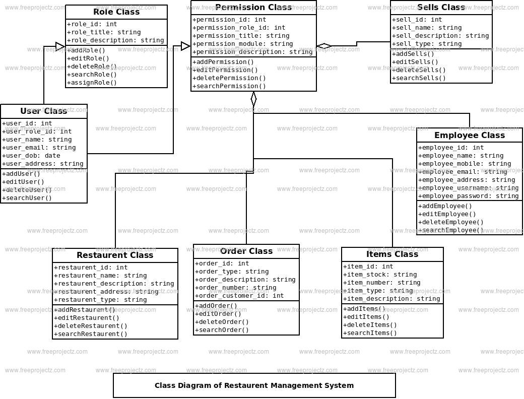
Here is the use case diagram of our Restaurant Management System: \n \n \n \n Use Case Diagram for Restaurant Management System\n \n Class Diagram \n. Here is the description of the different classes of our Restaurant Management System: \n \n; Restaurant: This class represents a restaurant. Each restaurant has registered employees.
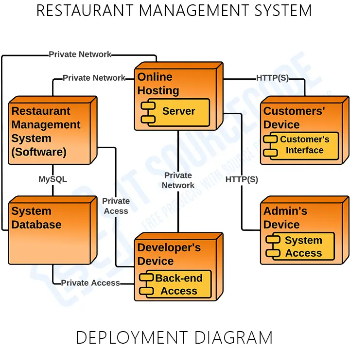
Deployment Diagram for Restaurant Management System UML
Restaurant Management System ERD (click to enlarge) To keep things simple, I have grouped this system into 4 sections. Menu Items - To address the elephant in the room, every restaurant definitely has a menu. Users - Staff and customers. Orders - "Sales". Transactions - Somewhat optional, as this crosses into a "financial system".
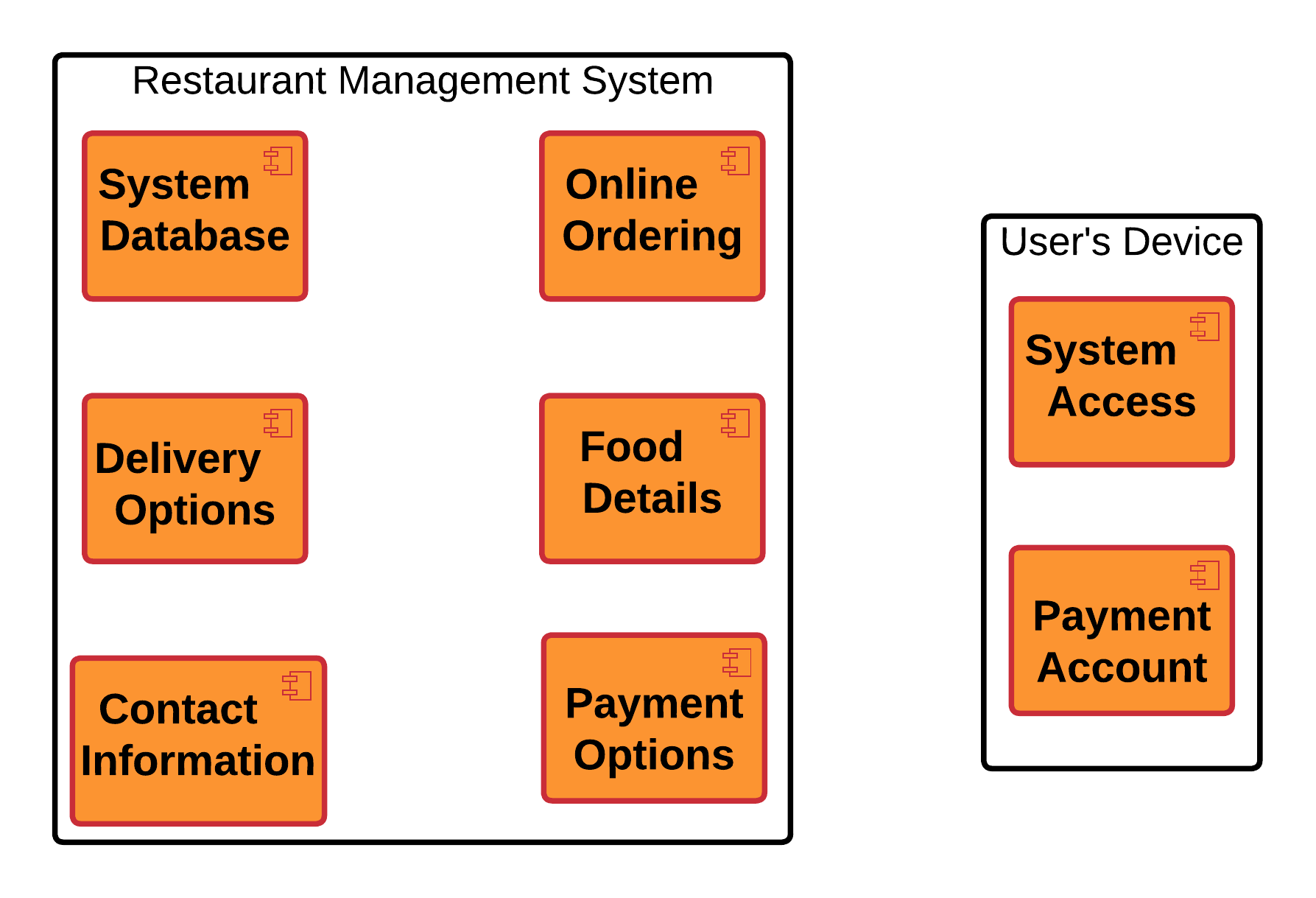
Component Diagram for Restaurant Management System
Here are the quick and simple steps to create a data flow diagram for restaurant management system using Wondershare EdrawMax: Step 1: Open EdrawMax and navigate to the template library. You can find the option on the left menu pane. Now, quickly type "DFD for Restuarant Management System" in the search bar and hit Enter. Step 2: Choose a.
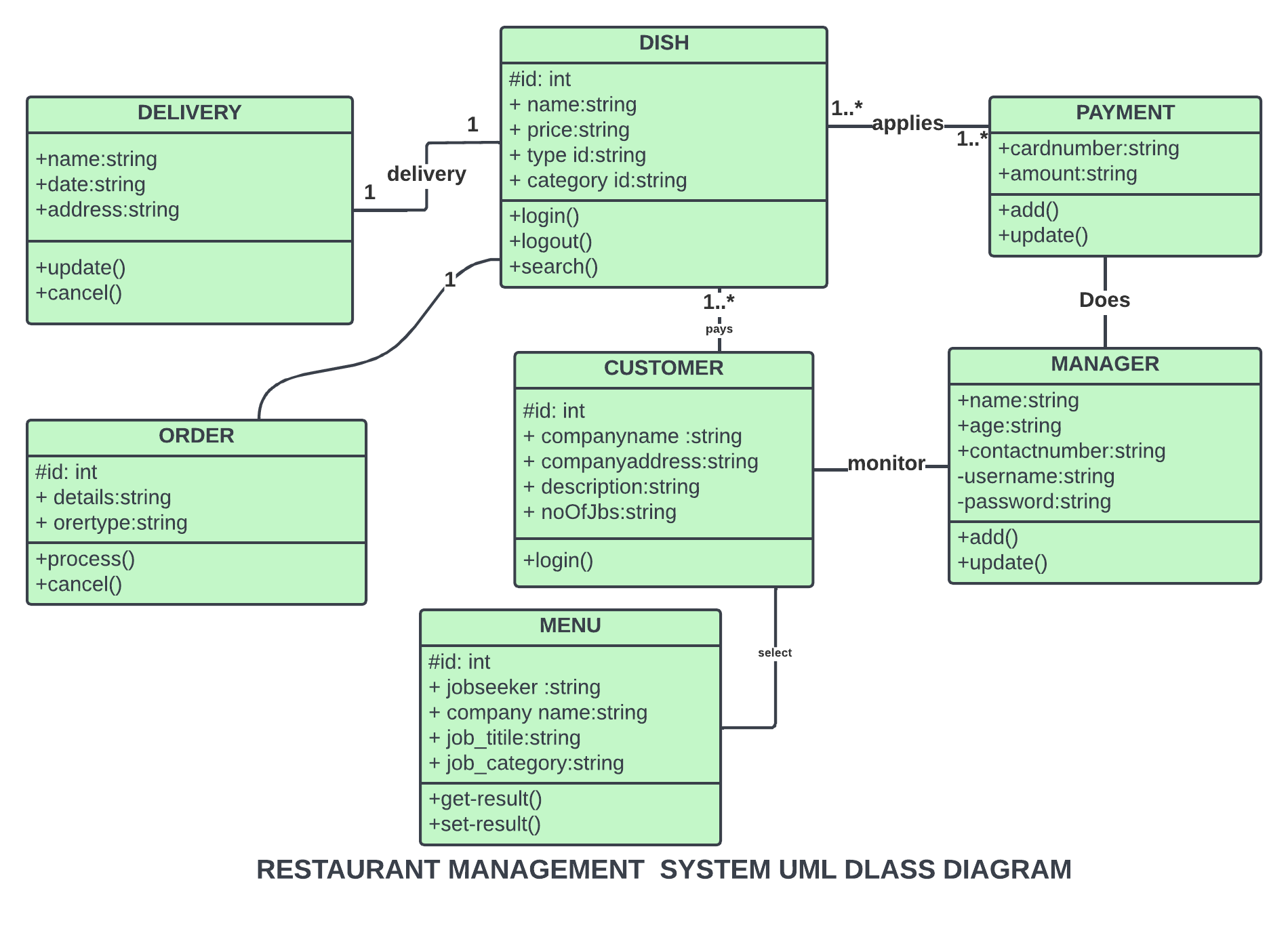
Class Diagram for Restaurant Management System
A deployment diagram for restaurant system in UML is used to illustrate its' physical architecture. In UML, deployment diagrams can show you how the software and hardware of the learning system work together and where the processing takes place. The restaurant management system uses a UML deployment diagram to show how should the developed.

Restaurant Management System UML Diagrams
Use Creately's easy online diagram editor to edit this diagram, collaborate with others and export results to multiple image formats. You can easily edit this template using Creately's class diagrams tool. You can export it in multiple formats like JPEG, PNG and SVG and easily add it to Word documents, Powerpoint (PPT) presentations, Excel or.
Restaurent Management System Class Diagram FreeProjectz
The syntax in Gleek to create a simple class like this is easy. Just type the word "Receptionist" then hit enter and the tab key to add the method "createReservation ()". The parentheses tell Gleek that this is a method. Gleek will draw your first class like this: That method enables the receptionist to create a Reservation.

Use Case Diagram Tutorial (Guide with Examples) Creately Use case
This is a Component diagram of Restaurent Management System which shows components, provided and required interfaces, ports, and relationships between the Restaurent, Sells, Payments, Orders and Employees. This type of diagrams is used in Component-Based Development (CBD) to describe systems with Service-Oriented Architecture (SOA). Restaurent Management System UML component diagram, describes.
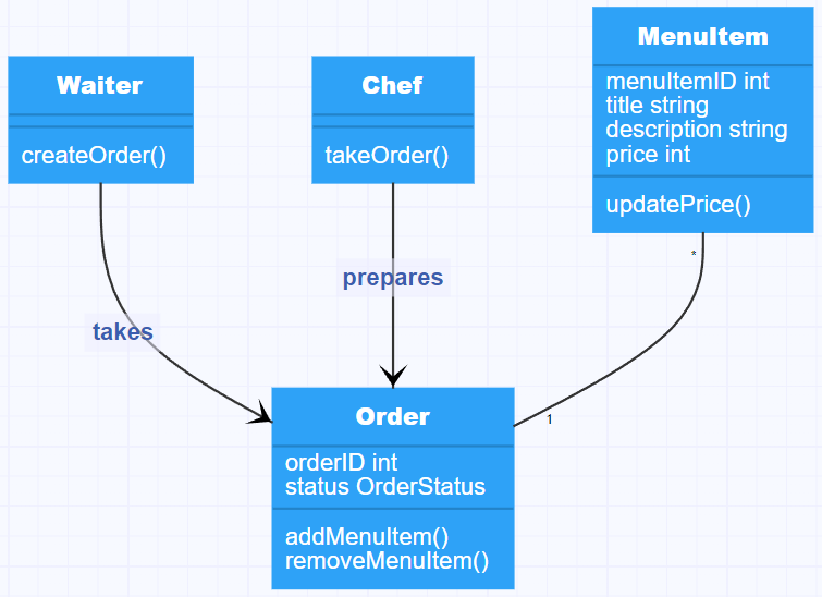
Restaurant management system class diagram from scratch Gleek
The component diagram of the restaurant management system has 7 components which are the system database, online ordering, food details, delivery options, contact information, payment options, system access, and payment account. This diagram shows several interfaces that are provided and required. The required interfaces (components) were on.
ER Diagram for Restaurant Management System
UML component diagrams bring simplicity to even the most complex processes. Take a look at the examples below to see how you can map the behaviors of specific processes with component diagrams in UML. Component diagram for a library management system. Library systems were some of the first systems in the world to become widely run by computers.

14+ Collaboration Diagram For Restaurant Management System Robhosking
Restaurants and cafes are popular places for recreation, relaxation, and are the scene for many impressions and memories, so their construction and design requires special attention. Restaurants must to be projected and constructed to be comfortable and e Component Diagram For Restaurant Management System
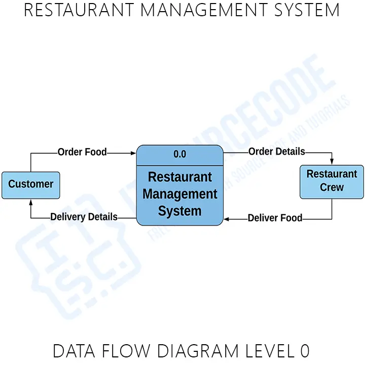
Restaurant Management System Dataflow Diagram
November 16, 2021 by Nym. RESTAURANT MANAGEMENT SYSTEM SEQUENCE DIAGRAM displays the participants that are included in the restaurant management system. It conveys the correct behavior and structure of a system before developing it. This contains the actors, objects, and messages that are plotted to illustrate the workflow of the UML Sequence.